OKAI Charging Station and ES400A/EB100B Connector Installation
Use this guide to take an OKAI charging-station delivery from unpacking through final commissioning. It covers three connected jobs:
- Assemble the control cabinet, charging piles, solar assembly, and docking bases.
- Retrofit OKAI ES400A scooters with the charging-station connector.
- Retrofit OKAI EB100B e-bikes with the charging-station connector.
The guide combines the manufacturer videos, the ES400A and EB100B service procedures, the shipment packing list, and the delivery notes in one field-ready workflow.
Qualified technicians only
This is an advanced mechanical and electrical installation. Vehicle work must be completed by a trained service technician. The station must remain de-energized and locked out until a qualified electrician completes and inspects mains wiring, protective grounding, and energization under the approved site plan and applicable local codes.
Before you begin
Work duration
| Workstream | Manufacturer procedure time | Crew |
|---|---|---|
| Charging-station assembly | 41-minute full procedure video | Installation crew plus qualified electrician |
| ES400A connector retrofit | 18 minutes per vehicle | Trained vehicle technician |
| EB100B connector retrofit | 15 minutes per vehicle | Trained vehicle technician |
Allow additional time for unpacking, site preparation, anchoring, electrical inspection, labeling, and testing every charging bay.
Safety and site requirements
- Barricade the work area and use appropriate PPE.
- Verify that the foundation, anchors, clearances, drainage, and electrical feed match the approved site plan. Those civil details are not included in the supplied OKAI package.
- Use a rated hoist, rated rigging, and the cabinet's designated lifting point. Never stand beneath a suspended load.
- Keep the station breaker open, isolate upstream power, and apply lockout/tagout before opening the cabinet.
- Remove the vehicle battery before either connector retrofit.
- Protect all connectors from dirt and moisture. Seat every waterproof gasket and coupling fully.
- Do not return a vehicle to service until steering, both brakes, lighting, charging, and all disturbed fasteners pass inspection.
Confirm the delivery
The supplied packing list describes one system with the following main items:
| Item | Quantity | OKAI part number |
|---|---|---|
| Control cabinet | 1 | 1040500004 |
| Charging-station assemblies | 10 | 1040700004 |
| Basement connectors | 9 | 4190002356 |
| Installation pack | 1 | 4190002351 |
| Solar pad | 1 | 4190002352 |
| Short basements | 11 | 4190002355 |
| Cabinet stem | 1 | 4190002353 |
| Charging-station battery | 1 | 2010100184 |
| Battery charging-converter cables | 80 | 2011300229 |
| EB100BV3 charger cables | 50 | 2011300151 |
Two loose items must be added
The delivery email identifies two items that may not be packed inside the container: one IoT unit shipped separately from OKAI headquarters, and two screws with part number 2040100604. Locate and stage all three items before installation.
Count each vehicle connector kit before disassembly. The kit should contain the model-specific connector, mounting bracket/base, adapter harness, required fasteners, and any sealing parts shown in the applicable procedure.
Tools
Station installation
Prepare the approved anchors and installation hardware, a rated hoist and rigging, hand tools and torque tools sized for the supplied fasteners, cable-pulling tape, an electrical multimeter, weatherproof sealant, labels, and lockout/tagout equipment. The station video does not publish fastener torque values; use the approved drawing or the fastener specification supplied for the site.
ES400A
- Electric screwdriver and adapter
- T20 × 100 hollow security Torx, T25 × 100, T30 × 50, and T40 × 50 bits
- 5 mm drill bit and drill
- Impact wrench
- Rivet gun and correct pop rivet
- Needle-nose pliers and brake-line pliers
- Flat screwdriver
- Blue Kafuter anaerobic threadlocker
- Calibrated torque tool covering 2–25 N·m
EB100B
- Electric drill/driver and adapter
- T20 × 75, T25 × 50, T30 × 100, and T40 × 50 bits
- 7 mm and 10 mm open-end wrenches
- 11 mm pentagonal socket
- Flat screwdriver and needle-nose pliers
- Cable puller
- Calibrated torque tool covering 1–25 N·m

Part 1: Install the charging station
Watch the complete station assembly once before beginning. Keep it available during installation for cable routing, connector orientation, and cabinet layout.
1. Stage and inspect the system
- Match all delivered components to the packing list and inspect them for shipping damage.
- Locate the separately shipped IoT unit and the two
2040100604screws. - Verify the foundation, anchor layout, upstream disconnect, grounding point, and cable entry against the approved site documents.
- Keep the upstream supply isolated and the station breaker open.
- Arrange components in installation order so cables and painted surfaces cannot be damaged.
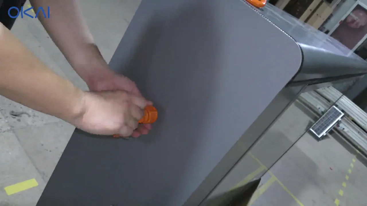
2. Lift the cabinet and install the mast
- Attach rated rigging only to the cabinet's designated lifting point.
- Raise the cabinet just enough to work safely around its base. Control the load throughout the lift.
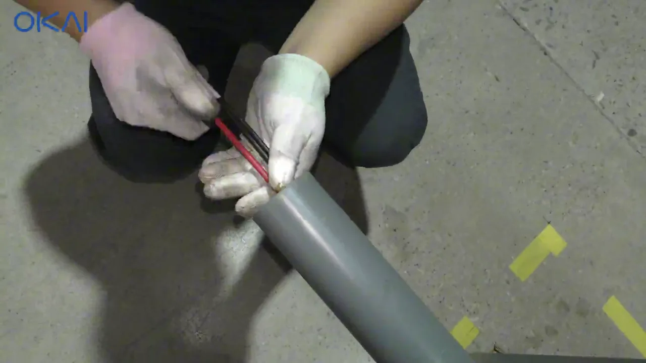
- Feed the mast cable through the mast. Use a pulling leader or tape around the cable body; do not pull on a connector or its conductors.
- Route the cable into the cabinet without twisting it, then seat the mast completely.
- Install and secure the mast hardware according to the supplied assembly drawing.
- Lower the cabinet into its final approved position and secure it to the prepared foundation.
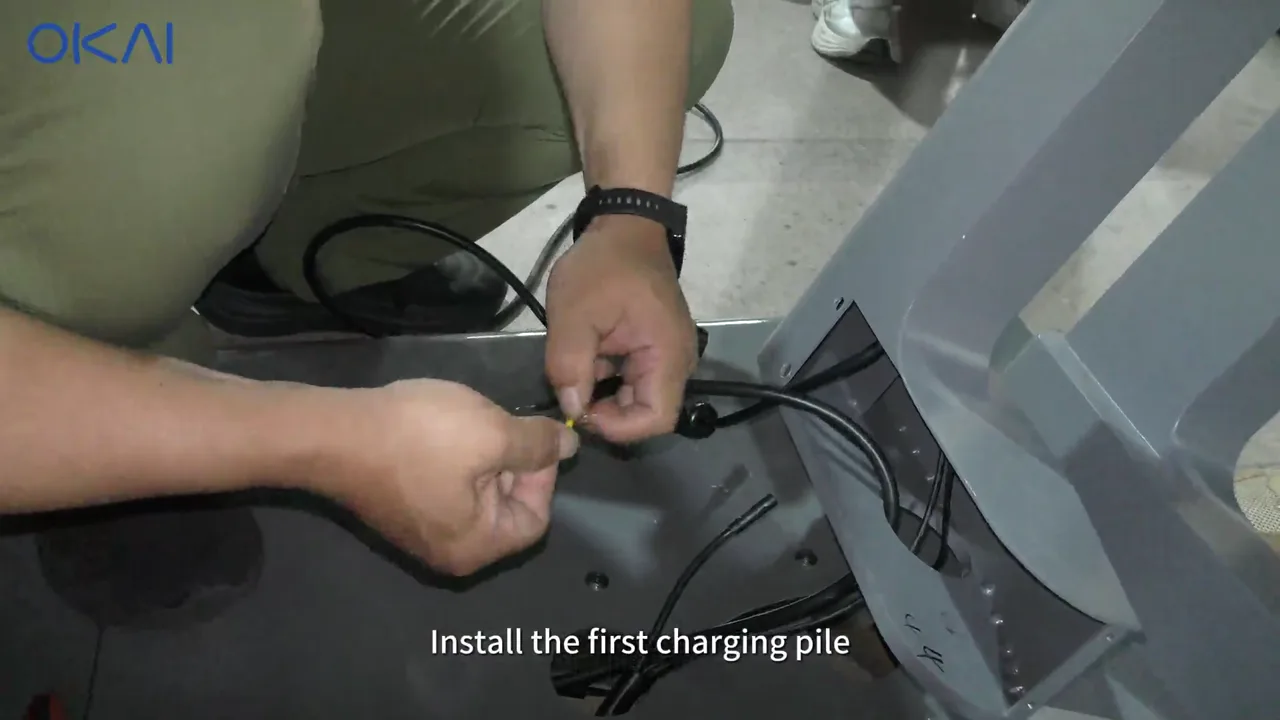
3. Install each charging pile
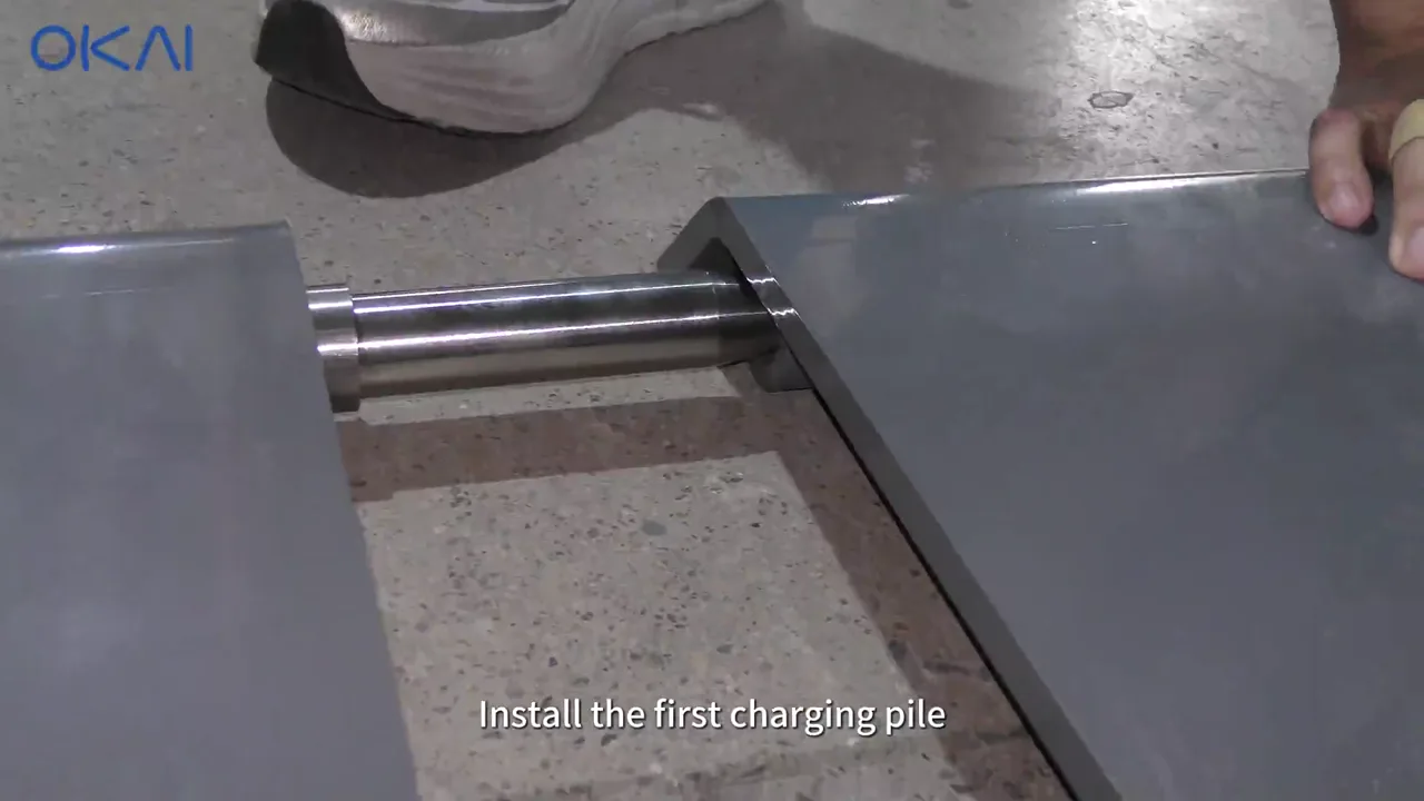
Repeat this sequence for every pile, working from the cabinet outward:
- Position the charging pile on its prepared base with the cable opening correctly oriented.
- Feed its cables through the base and toward the cabinet or adjacent connection point exactly as shown in the video.
- Seat the pile, align the mounting holes, and install the specified base fasteners.
- Match each keyed and labeled connector before mating it. Never force mismatched connectors.
- Push the waterproof connector halves fully together, engage the lock, and tighten the coupling collar by hand as designed.
- Dress the cable into the protected channel with a smooth service loop. Keep it clear of sharp edges, anchor hardware, and cover pinch points.
- Tug-test the connection gently and inspect the gasket/collar before moving to the next pile.
4. Close the lower bases
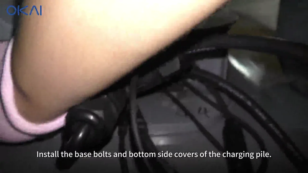
After every pile is connected:
- Recheck that no cable crosses a bolt hole, sharp edge, or cover seam.
- Install the remaining base fasteners.
- Fit the lower side covers without trapping a cable.
- Verify that every cover is seated evenly and that all exterior openings retain their seals.
5. Assemble the solar mast and panel
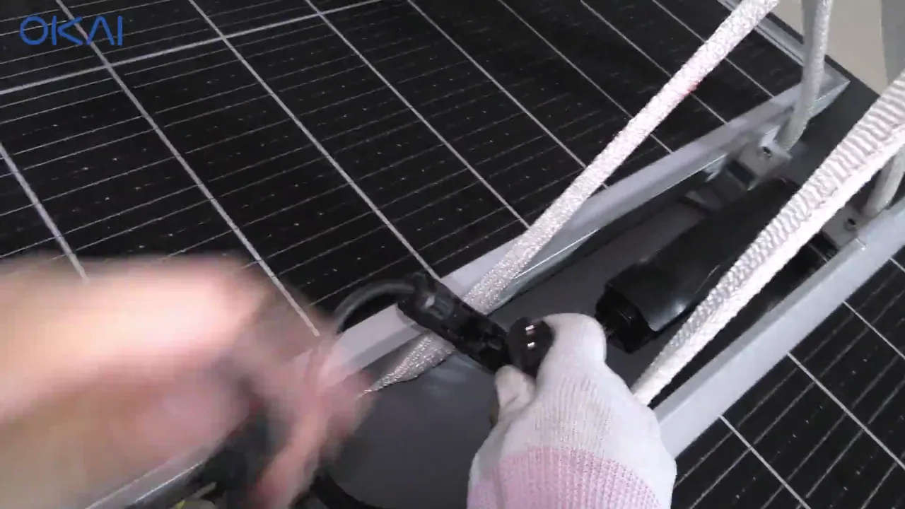
- Assemble and secure the solar-panel support using the supplied hardware.
- Route the solar cable through the mast without pulling on its connector.
- Match polarity and connector keys before mating the solar connections.
- Set the panel to the orientation specified in the site plan, then secure the mast clamp and panel hardware.
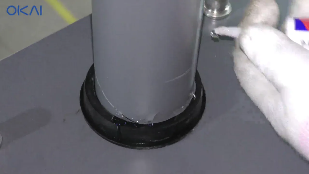
- Seal the mast penetration continuously with the specified exterior weatherproof sealant.
- Before energizing the cabinet, use a multimeter to verify polarity and that the solar source output is within the equipment specification. Do not use the video's example meter reading as the acceptance value for another site.
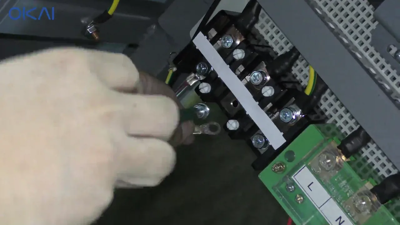
6. Complete cabinet grounding and wiring
Electrical stop point
From this point forward, cabinet work must be performed or directly supervised by a qualified electrician. Keep the upstream source locked out, verify absence of voltage with an approved tester, and follow the cabinet labels and site electrical drawings.
- Bring the approved supply and field cables through their strain-relieved entries.
- Connect the protective-earth conductor to the marked ground terminal before line or load conductors.
- Connect the internal harnesses and field conductors only to their labeled terminals. Maintain conductor separation and bend radius.
- Install the separately shipped IoT module using the two
2040100604screws and connect its labeled harness. - Torque electrical terminals to their manufacturer values, then perform a tug test and second-person inspection.
- Verify grounding continuity, polarity, insulation condition, and protective-device settings before closing the energized compartment.
7. Assemble the docking bases
- Arrange the short basement/base plates in their final sequence.
- Join adjacent plates with the supplied alignment pins/dowels and fasteners.
- Check that the complete row is straight, level, fully supported, and anchored as the site plan requires.
- Confirm every vehicle guide and connector is unobstructed and aligned with the corresponding charging pile.
8. Energize and commission the station
After the electrician authorizes energization:
- Record the cabinet, IoT, and charging-pile serial numbers.
- Apply power using the approved startup sequence.
- Confirm the cabinet display starts without a persistent alarm.
- Confirm the IoT module comes online in the expected management system.
- Inspect the displayed state for every bay; no bay should remain unexpectedly offline or faulted.
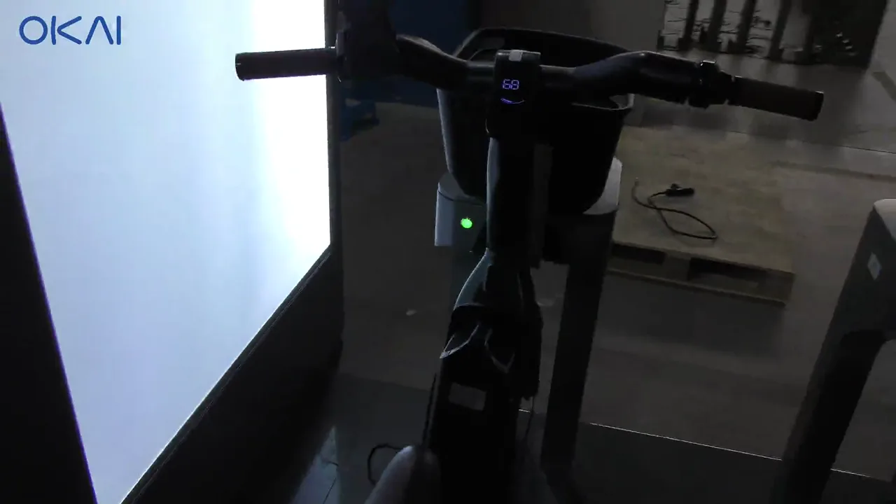
- Dock a known-good compatible vehicle at each bay and confirm the connector seats, the station detects the vehicle, and charging begins.
- Undock each vehicle and confirm charging ends normally.
- Close and lock all covers, remove installation debris, photograph the completed station, and retain the electrical test results.
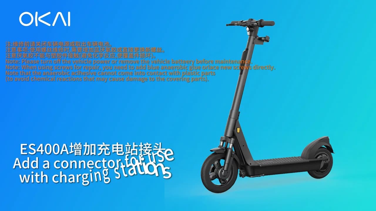
Part 2: Install the ES400A connector
The ES400A procedure has an estimated five-minute disassembly and 13-minute assembly. Download the original OKAI ES400A connector SOP PDF for the complete manufacturer step sequence.
1. Disconnect power and strip the stem
- Power the scooter off, disconnect the battery, and remove it from the vehicle.
- Pry off the left and right yellow reflectors with a flat screwdriver.
- Remove the front pedal pad and the five stem plastic-cover screws with T25.
- Remove the rear cover's two T20 screws.
- Release the rear brake-cable core screw with T30, then remove the spring and aluminum tail cap.
- Remove the three T25 cover screws.
- Release the front brake-cable core screw with T30, then remove its spring and aluminum cap.
2. Disconnect the controls and remove the handlebar/stem
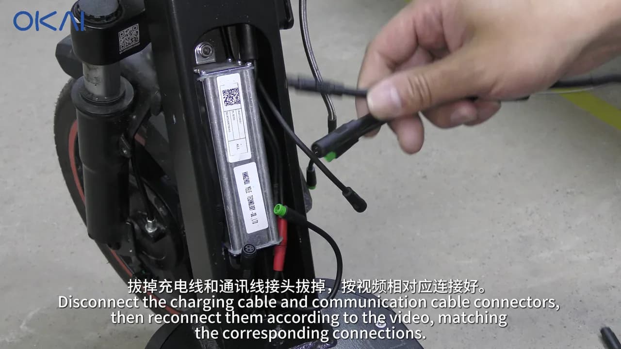
- Remove the controller/control unit's two T20 screws, unplug the control-unit connectors, and disconnect the communication cable.
- Remove the five handlebar-assembly screws with T25.
- Drill the existing pop rivet with a 5 mm bit, then push out the remaining rivet body.
- Loosen the three clamp screws with T40 and lift the headset/straight rod.
- Remove the clamp.
- At the fixing sleeve, remove the positioning screw, loosen the three sleeve screws with T30, and pull the sleeve upward.
3. Connect and route the charging adapter harness
- Match the charging, communication, and adapter connectors exactly as shown. Do not connect by wire color alone.
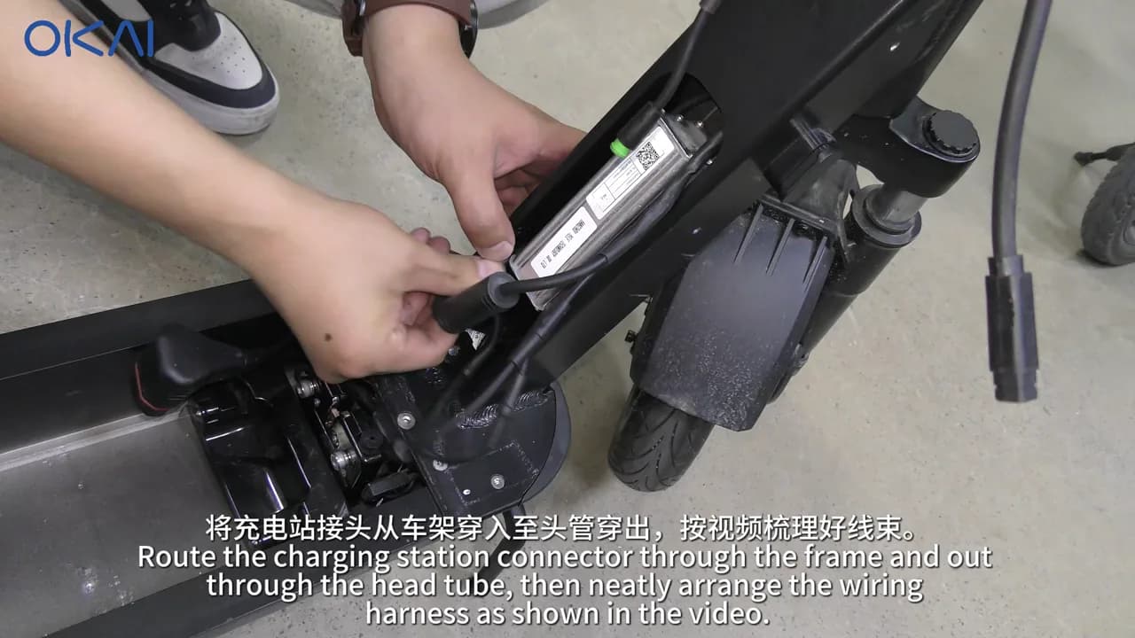
- Route the charging-station connector harness through the frame and head tube.
- Pass the harness and rear-brake housing through the fixing sleeve.
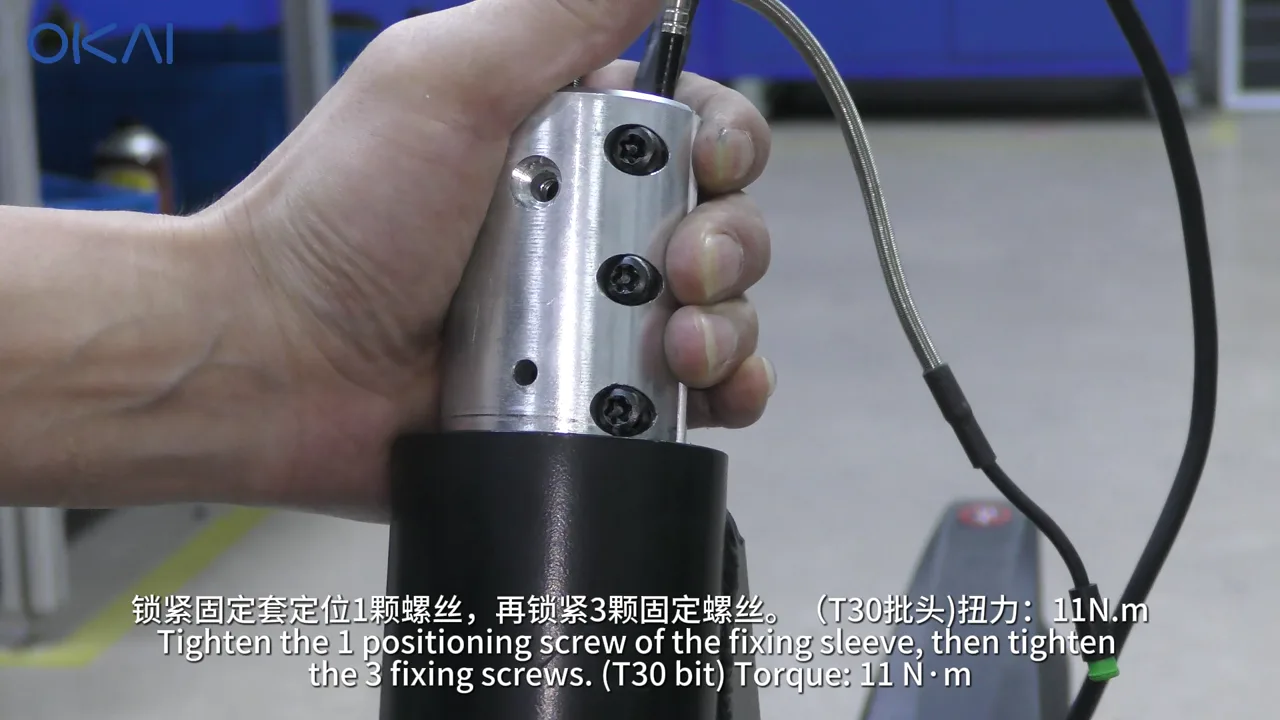
- Reinstall the sleeve's positioning screw first, then tighten the three sleeve screws to 11 N·m.
4. Reinstall the handlebar and feed the connector
- Orient the clamp with its positioning hole downward.
- Feed the front and rear brake cores and the new harness through the straight rod, then fit the handlebar clamp.
- Pre-tighten the three handlebar screws, install the remaining screws, and tighten all five sequentially with T25 to 4–6 N·m.
- Lift the straight rod, thread the brake cores and harness through it, and install it without pinching the wiring.
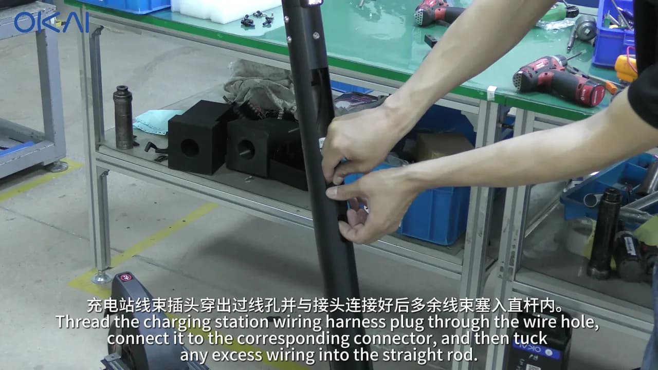
- Feed the charging connector plug through the stem's wire opening. Connect it and store the excess harness neatly inside the rod.
5. Mount the connector and restore the controls
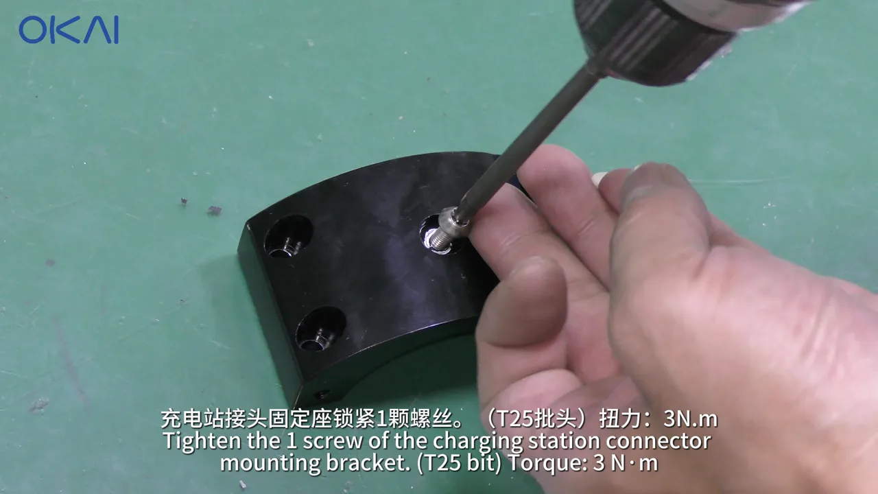
- Install the connector mounting bracket with its T25 screw at 3 N·m.
- Align the connector base's positioning screw with the locating hole.
- Install the four connector-base screws with T30 and tighten them to 9–11 N·m.
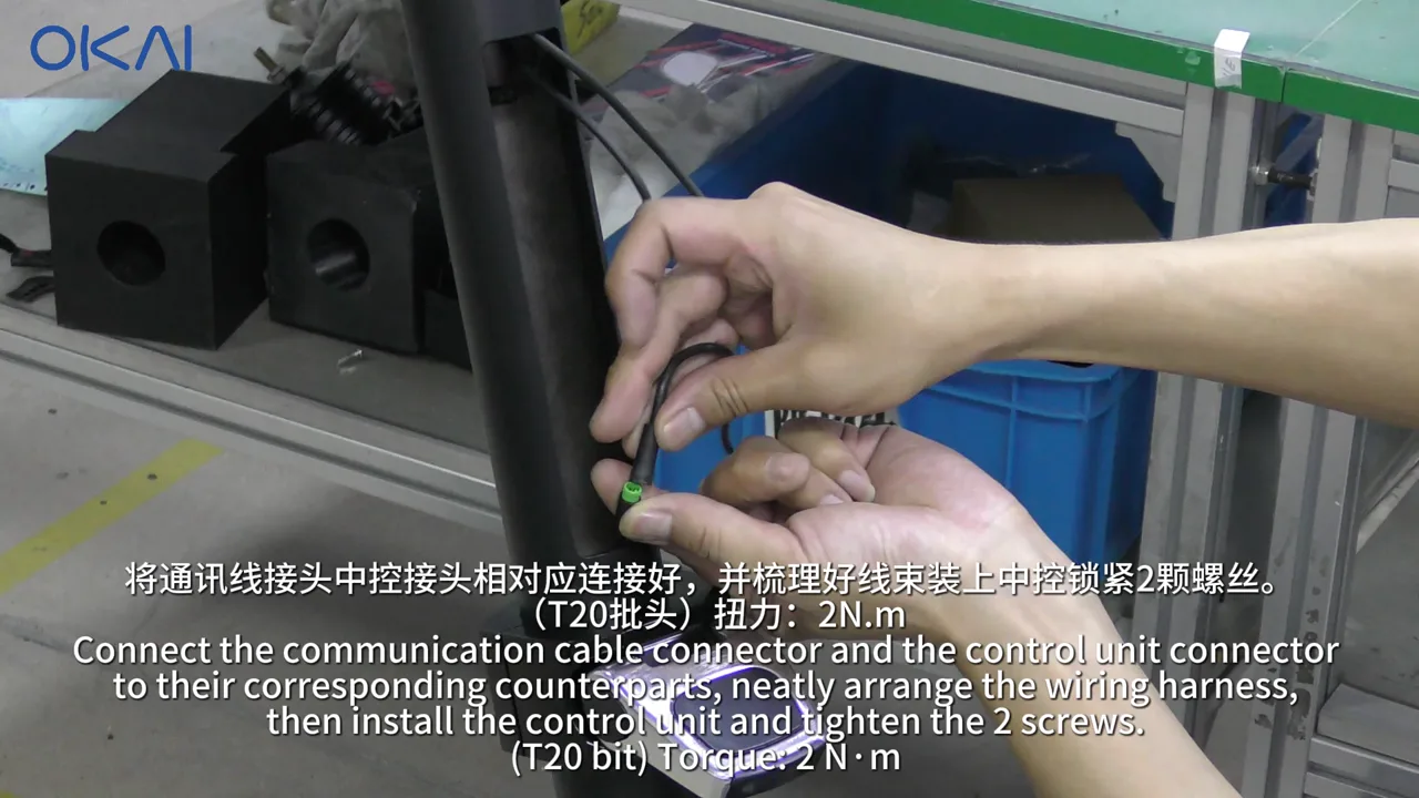
- Reconnect the communication and control-unit connectors.
- Dress the harness so it cannot be pinched, then install the control unit's two T20 screws at 2 N·m.
6. Reassemble and adjust both brakes
- Straighten both brake-cable cores with needle-nose pliers.
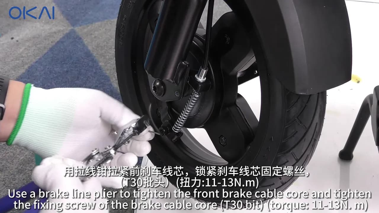
- Reinstall the front spring and apply blue anaerobic threadlocker to the front cable-fixing screw.
- Tension the front brake, then tighten the T30 fixing screw to 11–13 N·m.
- Squeeze the brake lever fully. The lever should stop 15–20 mm from the grip.
- Release the lever and spin the wheel. It must turn freely without pad rub. Readjust if either check fails.
- Reinstall the front aluminum cap, seat the cable in the spring, and install the three T25 cover screws at 3–5 N·m.
- Repeat the same sequence at the rear: spring, blue threadlocker, T30 cable screw at 11–13 N·m, lever check, free-wheel check, aluminum cap, and cable seating.
- Install the rear cover's two T20 screws at 3–5 N·m.
7. Secure the stem and finish the scooter
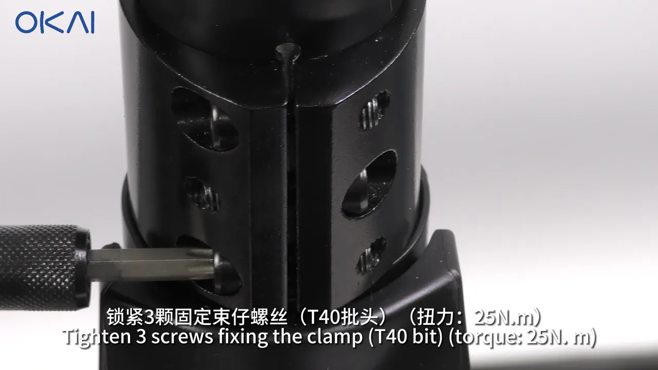
- Tighten the three T40 stem-clamp screws to 25 N·m.
- Install and set the new pop rivet.
- Install the stem plastic piece and front pedal pad. Tighten the first T25 screw to 3 N·m, then the remaining four T25 screws to 3 N·m.
- Apply the black adhesive pieces and reinstall both yellow reflectors.
- Reinstall and connect the battery, then close the battery cover.
ES400A torque reference
| Fastener | Tool | Torque |
|---|---|---|
| Fixing-sleeve screws (3) | T30 | 11 N·m |
| Handlebar screws (5) | T25 | 4–6 N·m |
| Connector mounting-bracket screw | T25 | 3 N·m |
| Connector-base screws (4) | T30 | 9–11 N·m |
| Control-unit screws (2) | T20 | 2 N·m |
| Front brake cable-fixing screw | T30 | 11–13 N·m |
| Front cover screws (3) | T25 | 3–5 N·m |
| Rear brake cable-fixing screw | T30 | 11–13 N·m |
| Rear cover screws (2) | T20 | 3–5 N·m |
| Stem-clamp screws (3) | T40 | 25 N·m |
| Stem plastic/pedal-pad screws (5) | T25 | 3 N·m |
Part 3: Install the EB100B connector
The EB100B procedure has an estimated five-minute disassembly and ten-minute assembly. Download the original OKAI EB100B connector SOP PDF for the complete manufacturer step sequence.
1. Disconnect power and remove the basket/battery base
- Power the e-bike off, disconnect the battery, and remove it.
- Remove the basket's three T30 screws and disconnect its electrical connector.
- Remove the mounting bracket's four T30 screws.
- Remove the bottom bracket's four T25 screws.
- Release the front brake nut and spring with the 11 mm pentagonal socket.
- Release the rear brake nut and spring with the 10 mm wrench.
- Remove the battery base's four T25 screws.
- Remove the battery fixing case's four T25 screws, then unplug the power and charging connectors.
- Remove the battery base's four T20 screws while holding the nuts with the 7 mm wrench.
2. Open the steering path
- Loosen the riser's three T40 screws and pull the riser upward.
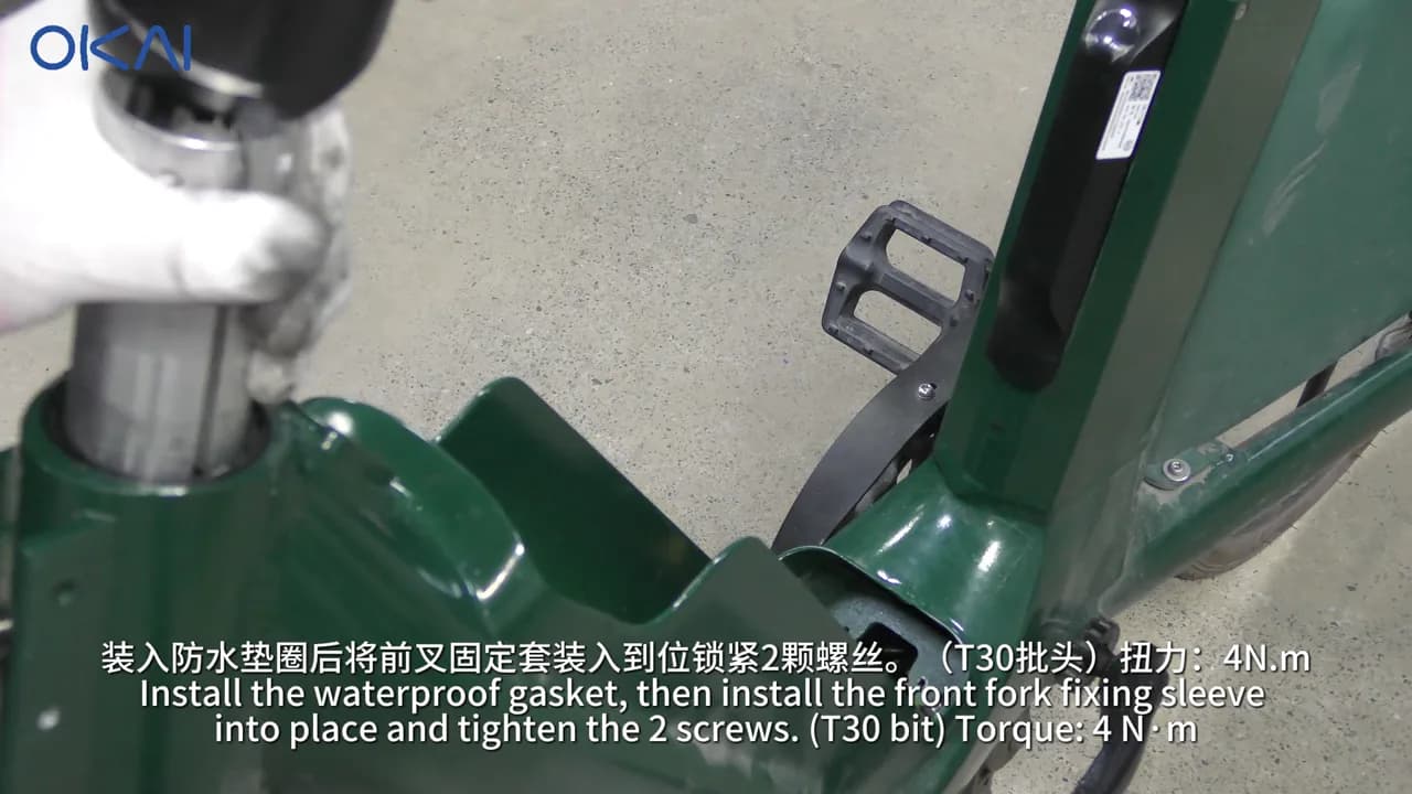
- Remove the front-fork sleeve's two T30 screws.
- Remove the two T25 screws and lift the remaining sleeve section.
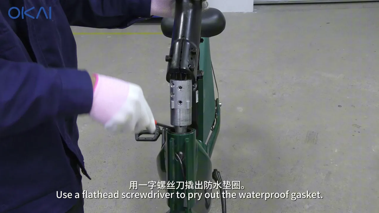
- Pry up the waterproof gasket carefully so it can be re-seated during assembly.
3. Route the adapter cable
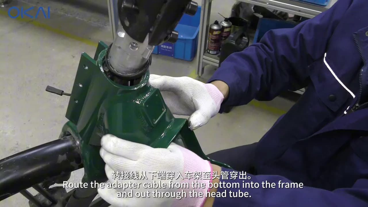
- Feed the adapter cable through the bottom of the frame and up into the head tube.
- Use the cable puller and flat screwdriver as shown to guide the connector down and out through the frame wire opening.
- Keep the cable away from steering and brake components and do not pull on the connector body.
4. Restore the waterproof gasket and riser
- Re-seat the waterproof gasket completely around the opening.
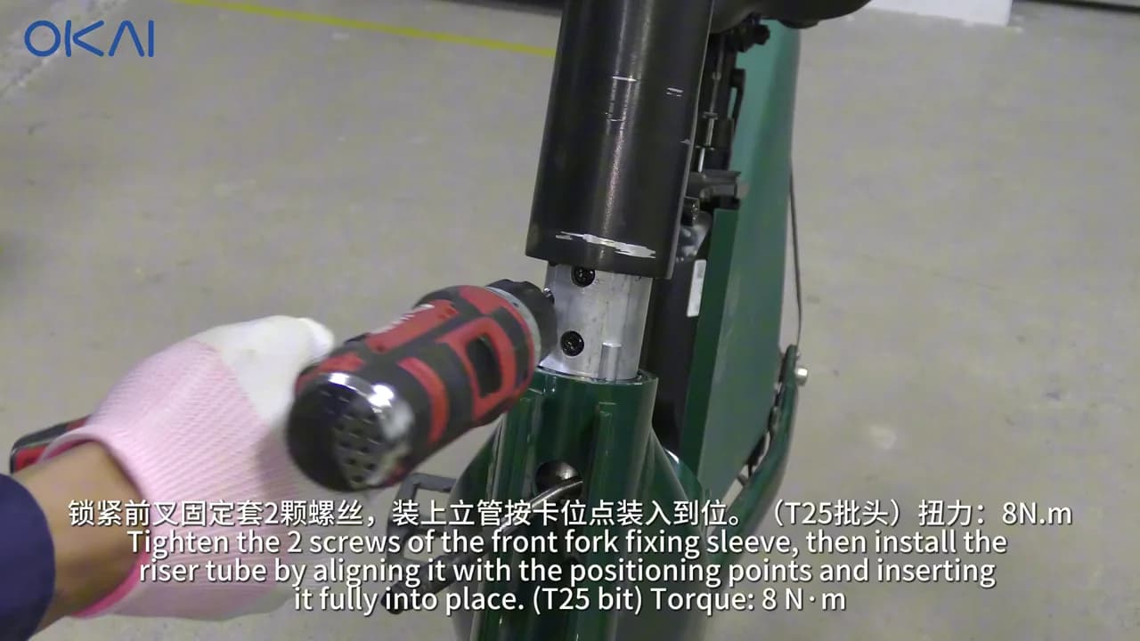
- Install the fork sleeve's two T30 screws at 4 N·m.
- Install the sleeve's two T25 screws at 8 N·m.
- Align the riser and push it fully into place before tightening the clamp.
5. Reconnect and adjust both brakes
- Seat the front brake housing in its locating hole.
- Install the spring, pre-tighten the nut, and feed the brake core through its hole.
- Adjust the front brake until the wheel spins freely without drum-brake noise, then tighten the 11 mm pentagonal nut to 8 N·m.
- Repeat the procedure at the rear and tighten the 10 mm nut to 8 N·m.
- Squeeze both levers repeatedly, release them, and spin both wheels. The brakes must apply firmly, release completely, and remain free of cable slip or rubbing.
6. Align and secure the steering
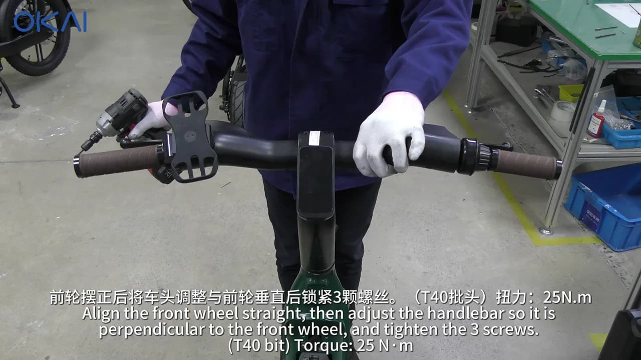
- Point the front wheel straight ahead.
- Set the handlebar perpendicular to the wheel.
- Tighten the three T40 riser screws evenly to 25 N·m.
- Recheck alignment and verify there is no steering play or cable binding from lock to lock.
7. Wire and reinstall the battery base
- Install the battery fixing case's four T25 screws at 2.5 N·m.
- Feed the power adapter cable into the battery base.
- Install the battery base's four T20 screws at 1 N·m while holding the nuts with the 7 mm wrench.
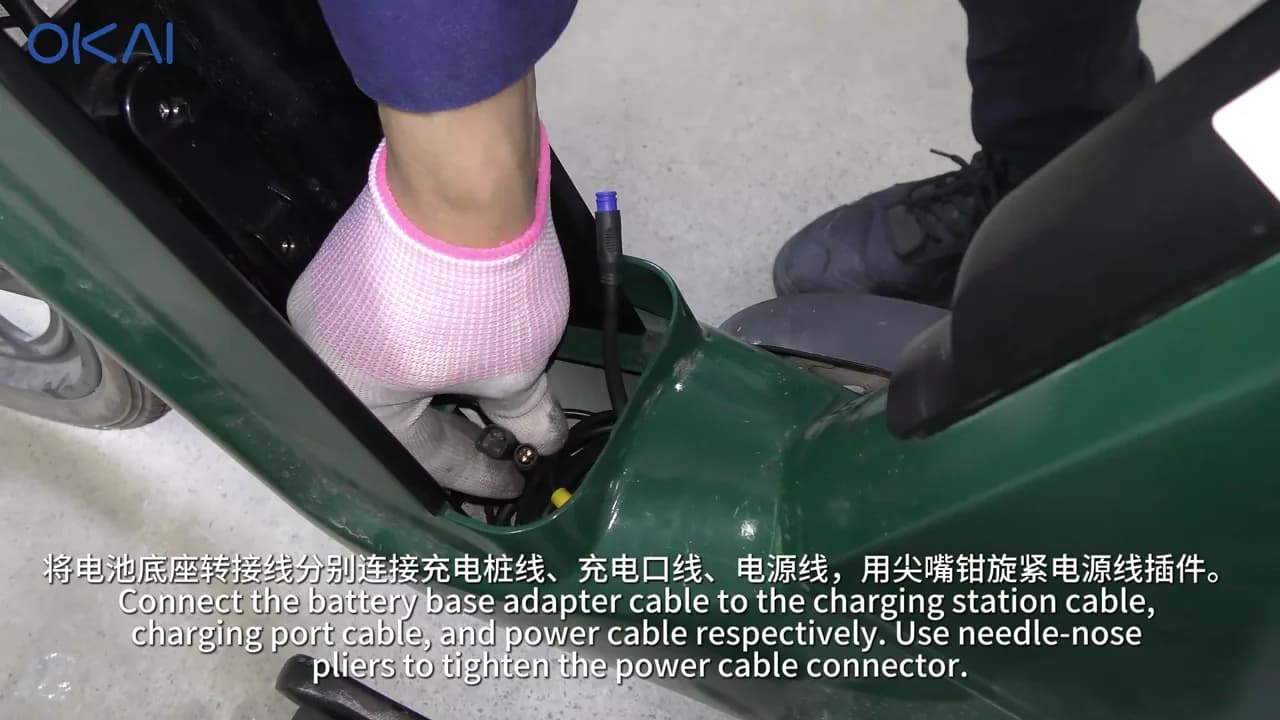
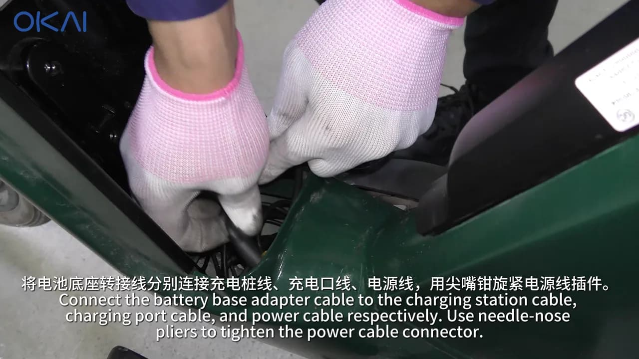
- Connect the adapter to the charging-station cable, charging-port cable, and power cable by matching each keyed connector.
- Use needle-nose pliers as shown to tighten the threaded power connector without twisting the wires.
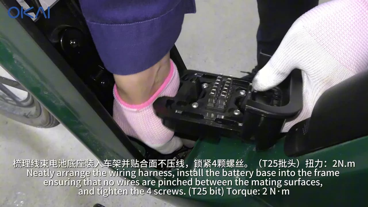
- Dress the complete harness into the protected cavity. Verify that no wire crosses a mounting surface or screw hole.
- Install the battery base's four T25 screws at 2 N·m.
8. Install the basket connector and finish the e-bike
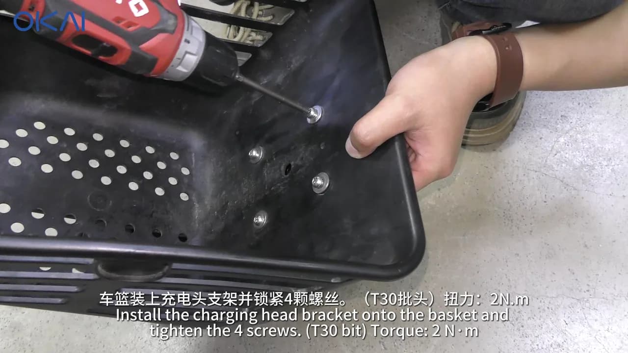
- Install the charging-connector bracket on the basket with the four T30 screws at 2 N·m.
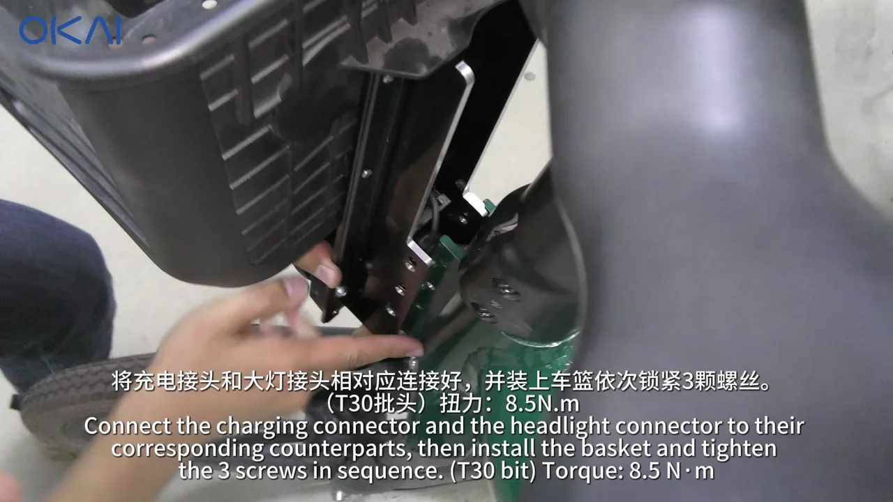
- Connect the charging connector and headlight connector to their corresponding harnesses.
- Position the basket without trapping either harness.
- Install the basket's three T30 screws sequentially and tighten them to 8.5 N·m.
- Reinstall and connect the battery.
EB100B torque reference
| Fastener | Tool | Torque |
|---|---|---|
| Front-fork sleeve screws (2) | T30 | 4 N·m |
| Sleeve screws (2) | T25 | 8 N·m |
| Front brake nut | 11 mm pentagonal socket | 8 N·m |
| Rear brake nut | 10 mm wrench | 8 N·m |
| Riser clamp screws (3) | T40 | 25 N·m |
| Battery fixing-case screws (4) | T25 | 2.5 N·m |
| Battery-base screws and nuts (4) | T20 + 7 mm | 1 N·m |
| Battery-base mounting screws (4) | T25 | 2 N·m |
| Basket connector-bracket screws (4) | T30 | 2 N·m |
| Basket screws (3) | T30 | 8.5 N·m |
Final commissioning checklist
Complete and document every item before handover.
Station
- Cabinet, mast, solar panel, charging piles, and bases are secure, aligned, and free of damage.
- All exterior penetrations, gaskets, connector collars, and mast seals are continuous and weatherproof.
- Protective grounding, terminal torque, polarity, insulation, and protective devices passed electrician inspection.
- IoT is installed, powered, online, and identified in the management system.
- Cabinet and every charging bay display a normal state.
- Every bay successfully detects, starts charging, stops charging, and releases a known-good compatible vehicle.
- All serial numbers, test results, and completion photographs are recorded.
- All cabinet and base covers are closed, fastened, and locked.
ES400A and EB100B vehicles
- Battery and all power/communication connectors are fully seated and locked.
- Harnesses have service loops and cannot rub, twist, pull, or become pinched.
- All disturbed fasteners are marked after torque verification.
- Waterproof gaskets and exterior connector seals are fully seated.
- Handlebar is aligned and steering moves from lock to lock without binding or play.
- Both brakes apply firmly and release completely; both wheels spin without brake rub.
- Headlight and other disturbed electrical functions operate normally.
- Vehicle docks without force, is detected by the station, and begins charging.
- Vehicle undocks normally and reports the expected charge state.
Troubleshooting
| Symptom | Checks |
|---|---|
| One bay is offline | De-energize, inspect that bay's keyed connectors and waterproof couplings, compare its routing with a working bay, then recheck cabinet indication after authorized restart. |
| Vehicle is detected but does not charge | Confirm model-compatible adapter harness, battery connection, charging-port connection, connector seating, station bay status, and battery state. Test with one known-good vehicle and one known-good bay to isolate vehicle vs. station. |
| Connector will not seat | Stop—do not force it. Inspect orientation, keying, bent pins, debris, bracket alignment, and whether the correct model-specific connector kit was installed. |
| Brake drags after retrofit | Recheck cable housing seating, spring and cap position, cable tension, lever travel, and the applicable 8 N·m or 11–13 N·m brake fastener. Repeat the free-wheel test. |
| Steering binds or pulls a harness | Open the affected covers, restore the specified harness path and service loop, then repeat alignment, torque, lock-to-lock steering, and brake tests. |
| Moisture path or damaged seal found | Do not energize or release the equipment. Replace the damaged seal/connector, dry and inspect the enclosure, restore the weatherproof joint, and repeat electrical safety testing. |
| IoT remains offline | Confirm the separately shipped IoT is the correct unit, both 2040100604 screws and its harness are installed, power is present at the designated connection, and the device identity is registered in the management system. |
Handover standard
The installation is complete only when the station passes electrical inspection, every bay passes a live charge test, and every modified vehicle passes steering, brake, lighting, waterproofing, docking, and charging checks.
Running a fleet on this hardware?
Levy Fleets runs scooters, e-bikes, mopeds and golf carts on the IoT hardware you already have, with integration pages for 29 vendors including Segway, Okai, Omni, Queclink, Invers and Comodule. Keyless unlock, geofencing, rider payments and rider support are included, and the Managed plan is a share of revenue with no per-vehicle software fee.